![]()
![]()
![]()
Freya Daughterboard
Introduction
Freya is a daughterboard ("DB") targeting custom mechanical keyboard printed circuit boards inspired by ai03's Unified Daughterboard. It integrates a USB type C connector and the proper RCC connectors needed.

Features
Freya integrates three main features: the protection circuitry, the cable-less (spring-loaded) connection to the main or mother board ("MB"), and the grounding of the case to which the DB is screwed.
Protection
Freya's protection circuitry uses a STEF05 electronic fuse ("e-Fuse") that protects the daughterboard and the main board from overload and overcurrent. It also protects the boards from power surges by implementing a voltage ramp through a 22pF capacitor on a programmable pin, setting the voltage ramp time to roughly 2 milisecondse The overcurrent protection takes place through e programmable pin using a 33-ohm resistor that sets the short-circuit current to roughly 2 ampères.
The e-Fuse also features an enable pin which should be left unconnected during normal operation; in Freya, this pin is exposed to allow for expanded usability.
Freya also integrates a Transient Voltage Supressor (TVS) on the USB VBUS power line and a USB data protection chip for additional reliability.
Cable-less MB connection
The connection between the DB and the MB takes place using a spring-loaded ("pogo pin") connector from Millmax. This connector allows a reliable connection between DB and MB without the use of a cable; the springs also allow the MB to bounce ("flex"). This means that a cable is not needed; therefore the end-user-assembly requires only screwing the DB into the case enclosure.
This feature however requires the PCB designer to align connection pads on the MB to the spring-loaded pins of the DB; see the "design guidelines" section for clarification.
Case grounding
In the mechanical keyboard community, most products are made with machines aluminum; therefore the majority of custom mechanical keyboards are made of metal that is often left non-connected. Freya integrates a ferrite bead that grounds the case through the screw, connecting it to the USB cable shield allowing for EMI and ESD protection.
Design guidelines
Choice of the pogo pin model
Millmax offers several options when it comes to the pogo pin choice. Freya is compatible with all surface-mount connectors with four pins and which pads are 0.1 inches (2.54mm) apart. The main difference among the models is their height and stroke -- respectively the maximum heght of the connector at zero force and this being the longest the pins can retract reliably from that position.

Figure 1 shows a sideview of the recommended connector model for Freya, 811-22-004-30-004101. This has a 6mm height with a 1.4mm full stroke (FS), meaning that with no force applied the distance between the PCB and the top of the pins is 6mm.
Millmax recommends that during normal operation the pins be used at half-stroke (HS), in this case 0.7mm, meaning that the case assembly must be designed with an optimal distance (OD) of 5.3mm, that is, a distance of 5.3mm between the top of the daughterboard PCB and the bottom of the main board PCB.
The table below shows some of the compatible connectors for Freya. The Full Height (FH) and Full Stroke (FS) parameters were taken from their respective datasheets; the Optimum Distance (OD) is calculated using
There are more compatible connectors, but they have needlessly large Optimum Distances which will most probably not be used in keyboard projects.
| Model Number | Full height (mm) | Full Stroke (mm) | Optimum Distance (mm) |
|---|---|---|---|
| 811 family | |||
| 811-22-004-30-000101 | 3.48 | 0.99 | 3.00 |
| 811-22-004-30-001101 | 4.49 | 1.14 | 3.92 |
| 811-22-004-30-002101 | 5.00 | 1.40 | 4.30 |
| 811-22-004-30-003101 | 5.51 | 1.40 | 4.81 |
| 811-22-004-30-004101 | 5.99 | 1.40 | 5.31 |
| 812 family | |||
| 812-22-004-30-000101 | 6.48 | 1.40 | 5.78 |
| 812-22-004-30-001101 | 6.98 | 1.40 | 6.28 |
| 812-22-004-30-002101 | 7.49 | 1.40 | 6.79 |
| 812-22-004-30-003101 | 8.00 | 1.40 | 7.30 |
| 812-22-004-30-004101 | 8.51 | 1.40 | 7.81 |
The choice of the pogo pin model depends primarily on the Optimum Distance; the mechanical constraints of the case design dictate how much distance between the DB and the MB is needed.
USB connector protraction
The type C USB connector protracts approximately 1.4mm from the edge of the PCB. It is recommended to keep a minimum 0.2mm distance from the PCB edges to any metallic part due to metal machining and PCB edge milling tolerances.
Screws
Freya inherits the same screw system than ai03's Unified Daughterboard version C3; hence the design guidelines here are identical:
Screws should be of M2 size, and at minimum long enough to clear the 1.6mm PCB substrate. Head diameter should be less than or equal to 4mm.
Lift the screw zones compared to the rest of the daughterboard area if using a metal chassis, so the metal case does not make flush contact against the entirety of the daughterboard. Only the screws and screw pads should make direct contact against the case; failure to do so may result in short circuit, and will most definitely not put the EMI suppression and chassis grounding circuits into proper function.
MB PCB pads alignment
The most difficult part of designing a Freya-compliant motherboard is aligning the connection pads. The motherboard should feature a four-pin through-hole connector which the spring-loaded connector heads will contact and make the connection. The connector also needs to be through-hole so that the user can use a four-pin header with which to reliably test the MB and the DB before assembling the keyboard without need to press the MB and DB one against the other.
Modelling
The Freya Resources repository contains a 3d_models folder where various STEP models of the DB can be found, each using a different pogo pin. The 811-22-004-30-004101 model is recommended.
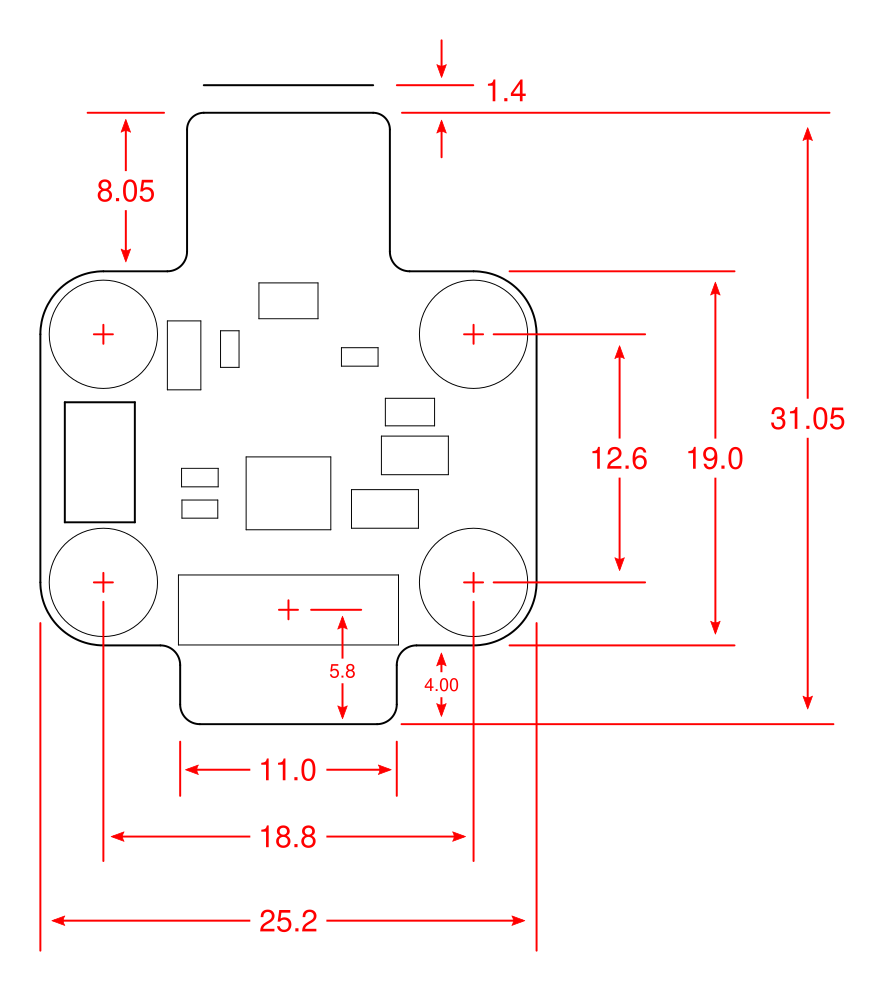
Dimensions
Usage guidelines
PCB testing
In order to thest the MB, the DB and the connection between the, use a 4-pin-header between the through-hole pins that should be on the motherboard and the through-hole-pins on Freya. Remember that the pins have a polarity: the square pads (which are 5V) on the DB and the MB should align.